
Марсом
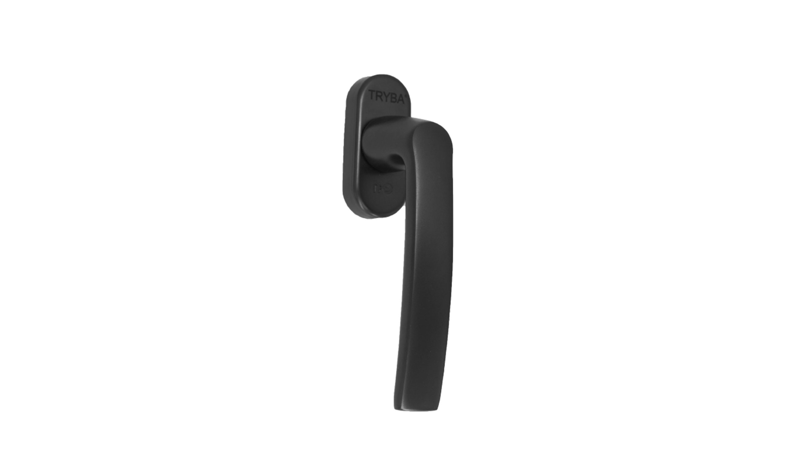
Как работает поворотно-откидное оборудование
Поворотно-откидной механизм соединяет многопозиционную ручку со стержнями, угловыми приводами и запорными кулачками вокруг открывающейся створки. В поворотном режиме створка поворачивается на оси боковой петли. В режиме наклона верхняя часть створки сдвигается внутрь, а ход ограничивается упором. В закрытом состоянии задействуются точки фиксации и нагружаются прокладки по периметру.
В этом примечании объясняется, что делает механизм и как читать полученные данные о производительности. В примерах описаны механические принципы. При выборе продукта следует использовать аппаратное обеспечение и полную документацию для предлагаемой сборки.
1. Кинематические степени свободы и три состояния перехода
| Handle position | Mechanical state | What the sash does |
|---|---|---|
| 0° · Down | Locked | Locking points engage in the frame keepers. |
| 90° · Horizontal | Turn | The sash rotates around its vertical hinge axis. |
| 180° · Up | Tilt | The top moves inward around the lower horizontal axis, within the stay’s travel. |
These positions describe one turn-before-tilt arrangement. Close the sash before switching modes. For a tilt-first or restricted-opening variant, follow the installed hardware instructions and identify the exact configuration in the schedule.
Idealized gear travel
For an ideal rack-and-pinion model, the travel relation is Δs = r × θ, where r is the pitch radius and θ is handle rotation expressed in radians. With a hypothetical 18.5 mm radius and a direct 1:1 relationship, the calculation is:
| Handle rotation | Radians | Calculated travel in the ideal model |
|---|---|---|
| 90° | π/2 | 29.1 mm |
| 180° | π | 58.1 mm |
These are calculated example values. They do not establish the travel of a G-U gear or the stroke of a particular rod. Product-specific travel requires the identified transmission geometry or measured displacement.
2. Трансмиссия: тяги по периметру и угловые шестерни 90°.
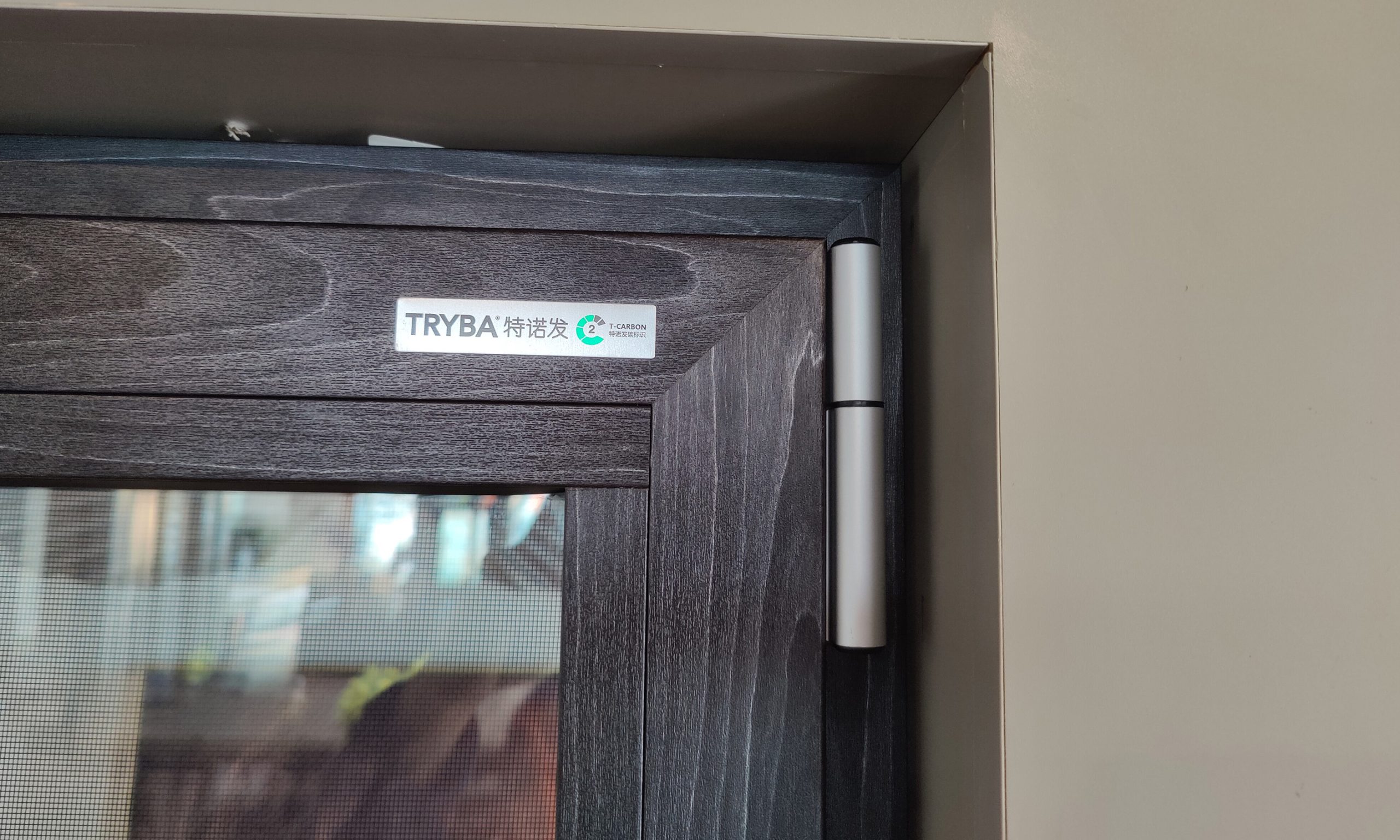
Drive rods transfer motion along the sash. A corner drive redirects that movement around the profile corner so the hardware can engage locking points on more than one edge. Parts and allowable layouts vary with the sash dimensions and hardware family.
A mishandling device can constrain operation when the sash is out of position. To confirm what is fitted, request a parts list or assembly drawing for the series. G-U’s UNI-JET technical drawing is a useful reference for how a manufacturer documents hardware variants and allowable assembly dimensions.
3. Геометрия ножничного рычага (Киппа-Шерена) и распределение нагрузки по центру тяжести.
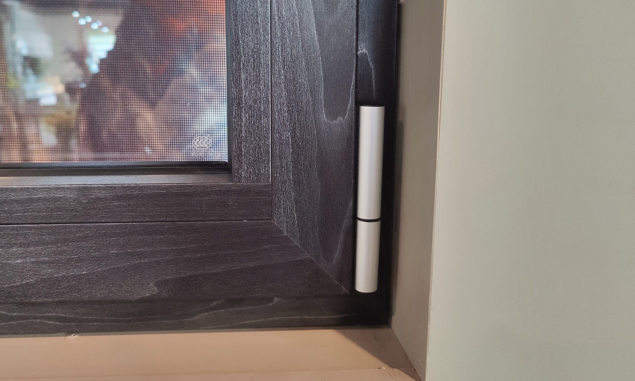
In tilt mode, the stay limits movement of the top of the sash, while the lower bearings and associated hardware support and locate it. The actual loads depend on sash mass, geometry, opening position, wind and how the hardware attaches to the profile.
Check permissible sash weight, width, height and glazing configuration against the hardware manufacturer’s application diagram. Use the specified stay and bearings together with the fastening and reinforcement details of the window system.
4. Механика сжатия по периметру: грибовидные кулачки и прокладки из EPDM
In the closed position, cams engage their keepers and draw the sash toward the frame. Gasket deflection is governed by profile geometry, gasket type, cam setting and assembly tolerances. Too little compression can leave gaps. Excessive compression can increase operating effort or damage components.
A gasket compression estimate describes a local mechanical condition. Air leakage and water penetration are whole-window properties. Assess them using applicable test reports that identify specimen dimensions, glass, hardware, test pressure and configuration.
5. Акустические характеристики: уплотнения, остекление и данные испытаний
Leakage paths around the sash can contribute to sound transmission. Perimeter sealing is one factor. Glass thickness, lamination, cavity size, framing and installation also affect the measured result.
| Acoustic figure | What it describes | What to verify |
|---|---|---|
| Frequency-band transmission loss (dB) | Sound reduction at a specific test frequency. | Check the measured spectrum and identify the complete sample tested. |
| STC | A single-number sound transmission class calculated from measured data under a prescribed method. | Check the stated test and rating standard, and the configuration and size of the sample. |
Under ASTM E413, STC is a single-number classification. If frequency-band measurements are supplied, label them as such and cite the test report. Do not substitute illustrative curves for product ratings.
6. Диагностика выравнивания створки и аппаратных проблем.
When the sash binds or rubs, identify the hardware model and record the location and mode in which it occurs. The permitted tool, direction and adjustment range depend on the hardware variant and sash configuration.
| Symptom | Information to collect | Document to use |
|---|---|---|
| Sash rubs at the sill | Record the rubbing point and measure clearances. | Manufacturer’s instructions for the lower bearing and installation. |
| Sash rubs at a side or top edge | Check frame alignment and note which mode is affected. | Hardware-specific hinge or stay adjustment instructions. |
| Handle is hard to close | Check whether the sash aligns and seats before locking. | Manufacturer’s cam and keeper settings for the fitted parts. |
Have an installer inspect a sash that is unstable, damaged or cannot close normally. Avoid applying a generic screw setting or adjustment range to unidentified hardware.
7. Сравнительная инженерная матрица: европейские поворотно-откидные механизмы и традиционные механизмы США/Австралии.
| Design aspect | Tilt-turn window | Crank casement | Horizontal slider |
|---|---|---|---|
| Operating mechanism | Side-axis swing and a separate tilt position. | Side-axis swing driven by an operator. | Sash slides along a track. |
| Seal and locking design | Perimeter hardware and seals depend on the specified series. | Seal and locking arrangement depend on the operator and frame. | Track, interlocks and weatherstripping vary by model. |
| Compare tested results | Request specimen and hardware details. | Check that the test method and specimen configuration match. | Compare under equivalent conditions and use the applicable report. |
The operating style helps explain movement and clearances. The tested specimen and its documentation establish any model-specific performance rating. See Trybawindows certificates and test reports for the available document index.
Ключевые выводы по архитектурным спецификациям
Specify the operating sequence, hardware model, permitted sash size and testing documentation together. Confirm the glazing and installation conditions that apply to the project before adopting a published test result.
Explore Trybawindows tilt and turn windows · European Tilt and Turn Windows Buying Guide · Contact Trybawindows